About the Project
For airplane enthusiasts, this project not only displays a nice wall picture of our local MSP (Minneapolis) International Airport, but also retrieves real-time information from ATIS (Automatic Terminal Information System) to determine how the runways are currently configured for Arriving and Departing planes. That information is displayed by tiny LEDs shining from behind the paper diagram.
The FAA DIGITAL ATIS information is free. (MSP airport code is: KMSP) https://atis.info/api/kmsp This information will be used to retrieve the latest runway assignments. If you were interested in displaying actual plane arrivals and departures, you would use an online service that costs money (for data access). The FAA DIGITAL ATIS website will be described at the end of this web page.
Find the latest PDF
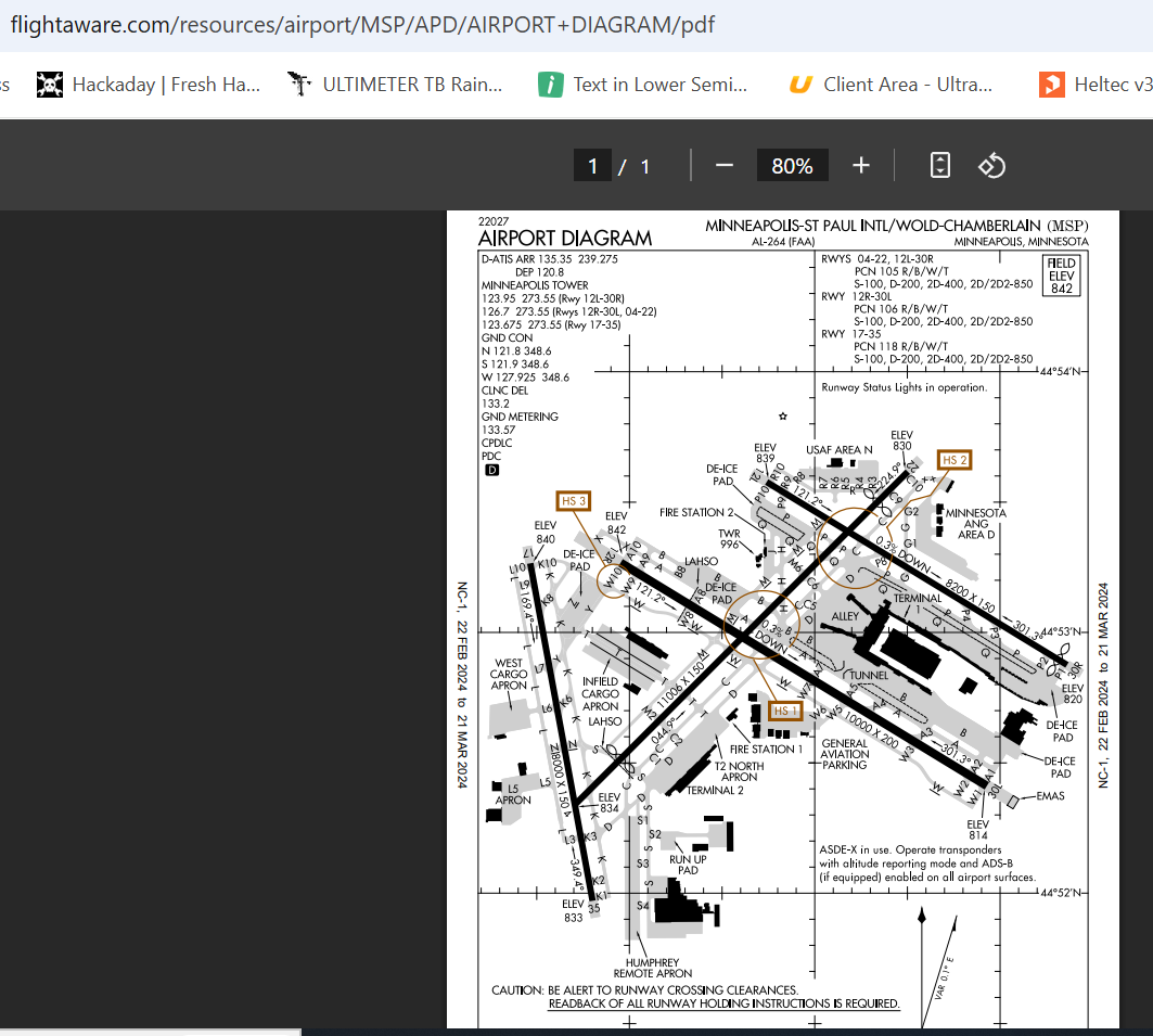
You can use FlightAware or other sources to find the latest PDF diagram of your desired airport.Link for the MSP Airport:
MSP Diagram PDF
Print out on 11 X 17 inch card stock (2 copies)
On a high quality color printer, load 40lb or 80lb card stock quality paper and print out a couple of copies of the airport diagram (PDF). You'll need one for the diagram you see framed and the other one for mounting the LED strips. In summary, you'll be using the first diagram to mount your LEDs flat, directly on the diagram. Later, you'll lay the other diagram directly on top and that diagram will be the one against the glass of the picture frame. The picture frame backing will press them both together.
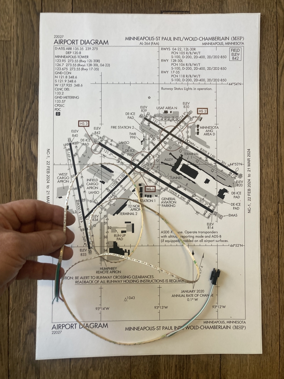
The Narrow LED Strip
On one of your images you will be laying out the LED strip alongside each runway. Cut holes in the diagram (with an xacto knife) and pass the LED strip under and back up, weaving your way around the diagram so the LEDs are as flat as possible on the top of the diagram.The LED strip has adhesive on the back of the strip. Don't worry about which LEDs are showing, in fact you can glue them on the entire runway (I glued mine alongside of each runway). The LEDs can be individually lit. In the end, you will be sandwiching the LEDs between this diagram and the other one you printed. Those LEDs will shine through the top diagram that you see in your final framed diagram.
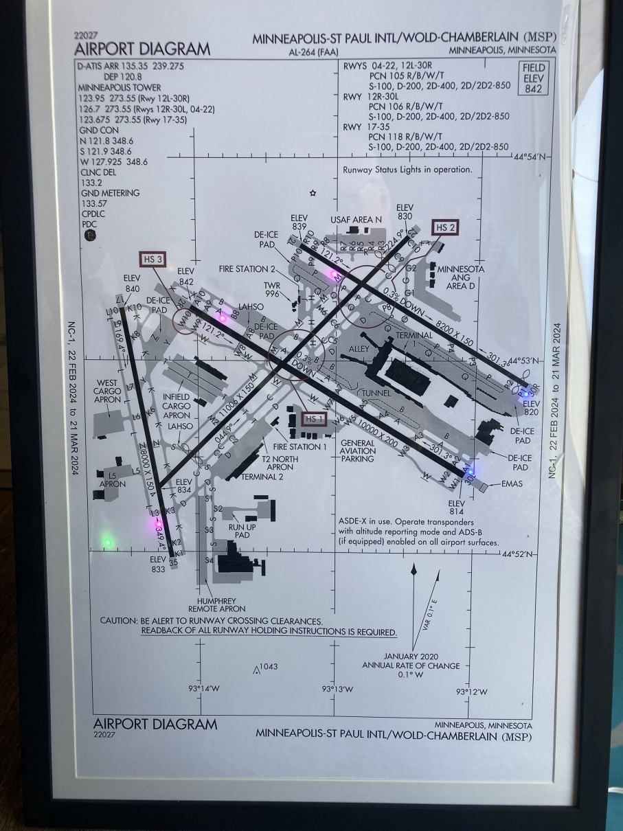
LEDs Shining Through
The final framed diagram has the LEDs shining through. They are animated showing blue for Arriving Runway and Purple for Departing Runway. Another LED (green) for status on whether or not the microcontroller was able to access data from the FAA DIGITAL ATIS website. https://atis.info/The API (Application Programming Interface) used for the ESP32 is from this URL:
https://atis.info/api/KMSP
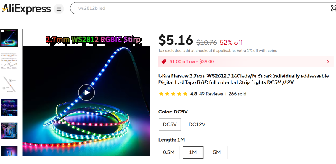
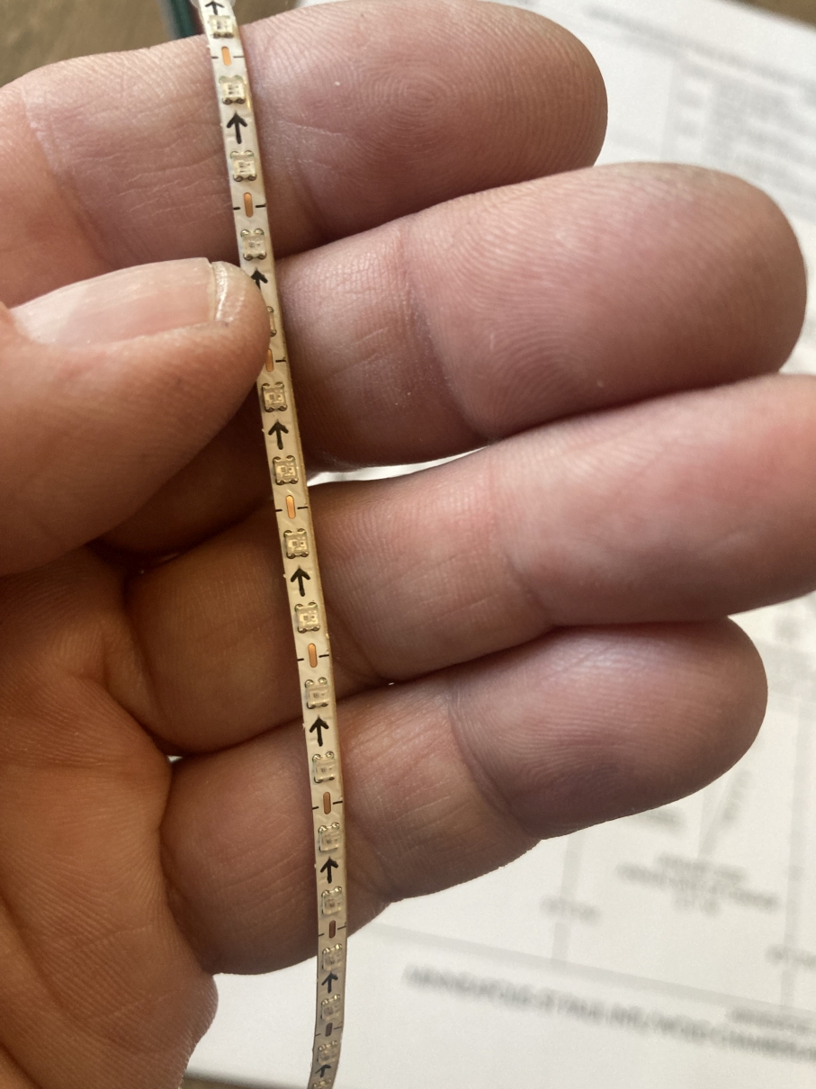
The LED Strip
This is what the LED strip looks like. I purchased a 1 meter length and it worked for my diagram. Other airports might have more runways and you'll need to buy the next size length (5 meter). You purchase one strip and use what you need. Any extra can be cut off. The LED strip contains many LEDs wired in series. Only a small number of the LEDs will actually be used. The microcontroller will send out an entire sequence of bits to address only the LEDs that it needs to light-up. You can glue the strips to any other part of the diagram for indicating other things (future programming).
LED Strip Animated
I mounted mine along-side each runway and extended a couple of LEDs past the end of each runway. Once the strip gets past the end of a runway, I pass the strip through a hole cut in the diagram and thread it back up to the end of another runway. Weaving it all around until you have both ends of the LED strip coming out the back of the diagram.
How will the LEDs be used ?
Once the LED strip is mounted on the diagram, you will use a pencil to mark six of the LEDs on the end of every runway. Those six LEDs will be blinking in a certain color to indicate arriving or departing traffic (see the animated GIF). Pick 6 for each end of the runway and then you will be counting them.
On the LED strip, you'll see tiny arrows printed on the flexible LED circuit board. This is the direction of flow for the LED data. The arrows are pointing to the end of the strip. You'll find the other end (the beginning) and count from 0 (zero) to the LED that appears on the first runway you did. Write that number on the diagram (with pencil). Keep counting and write down the numbers (addresses) of each set of 6 LEDs on your diagram. You will be using those addresses when programming the microcontroller to light the correct runways.
Any extra LEDs that are under the diagram can be brought to the top and stuck down to use as a status LED or for any other use. I just have one LED on the side lit as green or red to indicate valid or invalid data.
The ESP32 Microcontroller
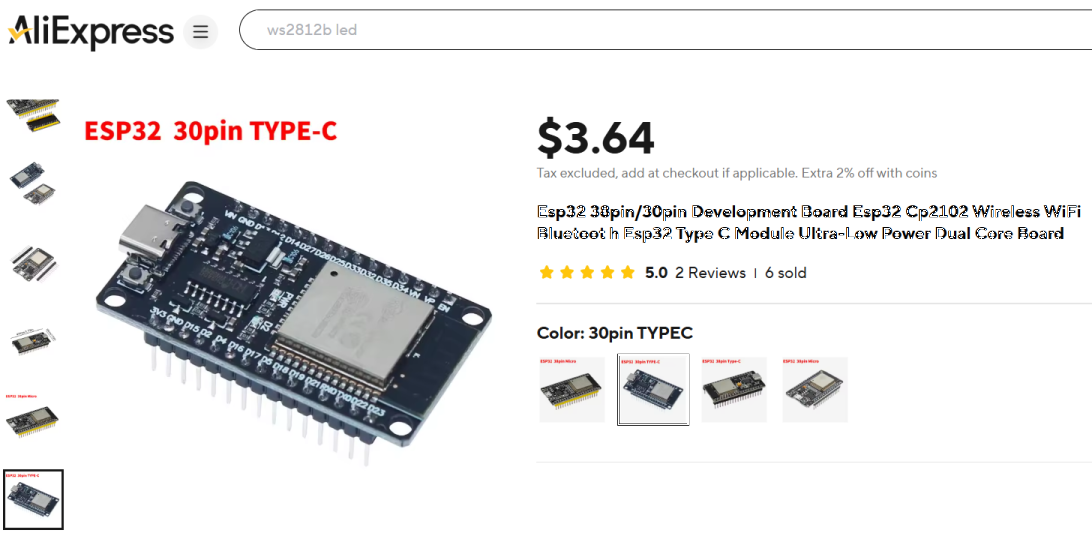
The brains of this is the ESP32 WiFi Microcontroller. Purchased from AliExpress. You'll most likely be using an Arduino IDE for programming. The sketch is available in the footer of this page ... download .txt file.
There is no way to describe the whole programming process in detail. The Arduino sketch contains libraries for a captive WiFi so you can teach the ESP32 your home Wifi login. That only has to happen one time. After that, the ESP32 will do its own thing.
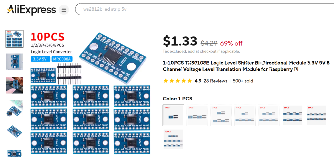
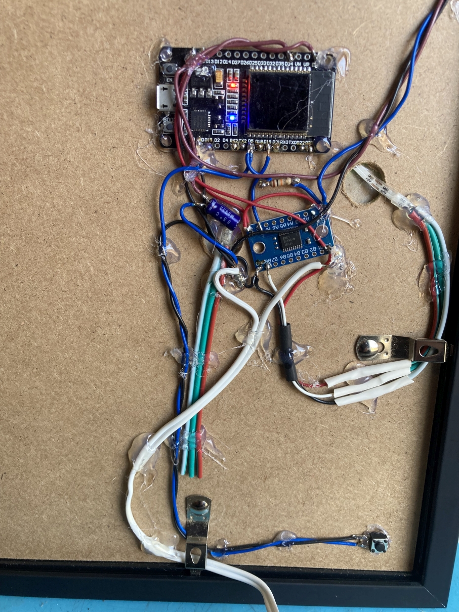
Other Hardware
Another tiny circuit board is used to power the 5V LED strip. The ESP32 operates output pins at 3.3V. That means it cannot directly power and stream data to the LED strip. The "level converter" board takes care of the differences in voltage. Another tiny board is used as a light sensor. It is mounted on the diagram with the LEDs glued to it. I punched a hole in the top diagram so the light sensor is directly behind the glass. It will allow the LEDs to brighten when the ambient like it bright. A small momentary pushbutton is used as a test button. It will light all of the LEDs on all of the runways. I used that mostly to align the two diagram sheets when they are sandwiched together. There is a small toggle switch mounted on the side of the picture frame. This will turn off the LEDs if you don't want them on at all (on off switch).
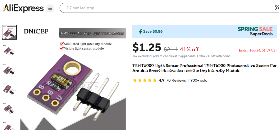
This is the level shifter ... 3.3V to 5.0V
This is the ambient light sensor.
Here is the back of the frame. The on/off switch was not mounted when this photo was taken.
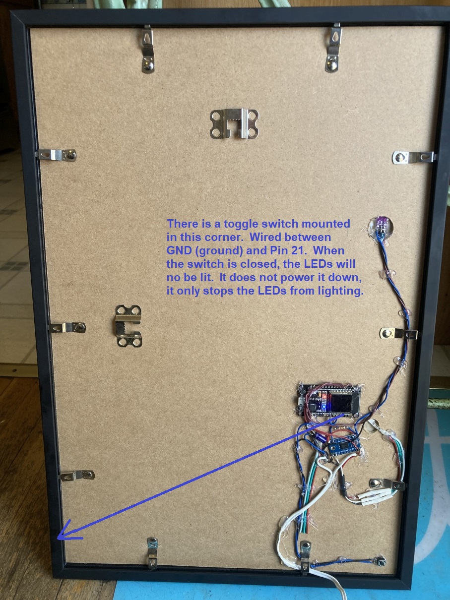
Back of Frame - ESP32 Mounting
All of the electronics are hot-glued to the back of the picture frame. The power supply is a wall-wart, 5VDC power supply connected to the 5V input pins on the ESP32. The frame is 12 X 18 inches with an included matted piece that allows mounting of the 11 X 17 inch airport diagram. The electronic portion was then covered with thin cardboard for protection.
How the ESP32 gets data from FAA DIGITAL ATIS
The ESP32, after connected to your WiFi, the ESP32 will access data from the FAA DIGITAL ATIS website. https://atis.info/If you only need to know how to get ATIS data using your ESP32, this example is how data is read for MSP airport. I discovered that the ATIS text is different for each airport. It seems like different people create the verbiage used. You have to determine which keywords are used and how to pick out the specific text.
This text file is the ESP32 Arduino IDE sketch used to get data: https://catpin.com/airport/atis.txt
If you were interested in displaying actual plane arrivals and departures, you would use an online service that costs money. Here is one of those sites that offer an API (Active Programming Interface): fr24api.flightradar24